1. How it works
The four-wire resistive touch screen is mainly composed of two layers of film coated with ITO coating. One layer has a vertical bus on the left and right edges of the screen, and the other layer has a horizontal bus on the bottom and top of the screen. If a voltage is applied to the two buses of a film layer, a uniform electric field will be formed on the ITO coating. When the user touches the touch screen, the two layers of film will contact at the touch point, and the voltage value of the contact point can be measured on the other layer of film (Figure 2.1). For measurement in the X-axis direction, the left bus is offset to 0V and the right bus is offset to VCC. The top or bottom bus is connected to the ADC, and a measurement can be made when the top layer and the bottom layer are in contact. For measurement in the Y-axis direction, the top bus is offset to VCC and the bottom bus is offset to 0V. The ADC input is terminated to the left or right bus and the voltage can be measured when the top layer is in contact with the bottom layer. For example, 2.1, the measured voltage is linearly related to the position of the contact point, which means that the X and Y coordinates of the contact point P can be calculated by VPX and VPY, respectively. In the actual measurement, the control circuit will alternately apply VCC voltage to the X and Y electrode sets to perform the voltage measurement and calculate the coordinates of the contact points.
The measurement process is illustrated by an example. In the first step, VCC is applied on X+ and 0V voltage is applied on X- to measure the voltage VPX on the Y+(or Y-) electrode and calculate the X coordinate of the contact point P; In the second step, VCC is applied on Y+ and 0V voltage is applied on Y- to measure the voltage VPY of the X+(or X-) electrode and calculate the Y coordinate of the contact point P; The above two steps constitute a measurement period, which can obtain a set of (X,Y) coordinates.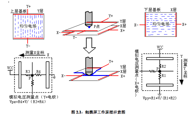
2. Linear calculation
The linear calculation is mainly to test the percentage difference between the actual voltage value and the theoretical value. Before the test, the linear tester determines the actual voltage of the four corners of the AA zone and the total voltage of the effective zone (V), first calculates the theoretical voltage (V2) at the line rail of the linear tester according to the measured actual voltage of the four corners, and then uses the line to determine the difference between the actual voltage (V1) and the theoretical voltage (∆V). The percentage of voltage difference (∆V) and total voltage (V) is then calculated, and the point with the largest difference across TP is our linear value
Linear is delta V over V


